Brian Simpson - Lagonda 2.6 DHC Column Change Gear Linkage Modification
Brian Simpson the author of this article is a very keen enthusiast; he is not a member of the Lagonda Club.
This is a guide only and no responsibility can be accepted for owners carrying their own work using this guide. No liability will be accepted for any reliance placed upon any information contained in this article.
Remove the gearbox cover from the floor of the car to gain access to that end of the gear linkage fixings. Remove all the linkage rods.
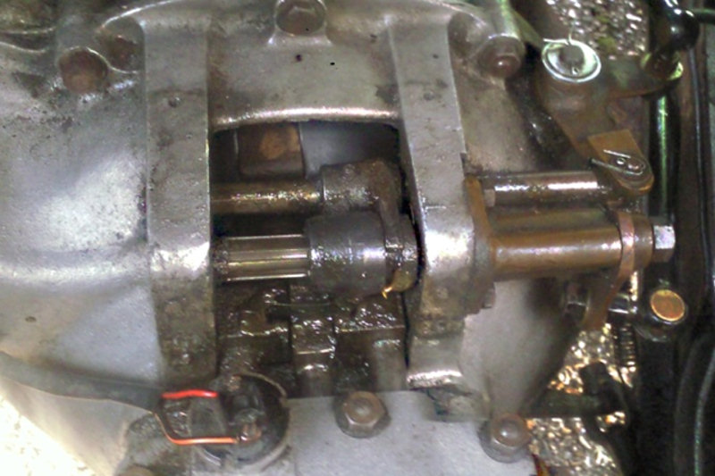
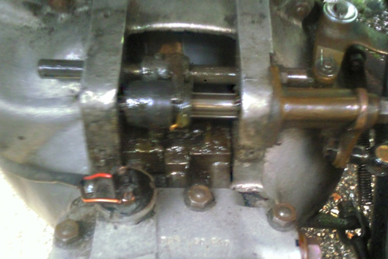
When re-fitting the linkage remove the small cover on the gearbox over the ends of the selector rods. Fit the linkage back on the car but only lightly tighten the nuts.
If necessary adjust the rods so that when the gear lever is moved into its various positions the selector engages with its correct selector rod. Make sure that the selector pin is not trying to move two rods at the same time, which will happen if the pin is not centred in one rod but overlaps slightly onto another one.
Gear linkage that is not adjusted correctly is probably a more frequent cause of gear selection problems than the gearbox itself.
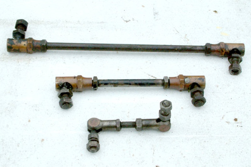
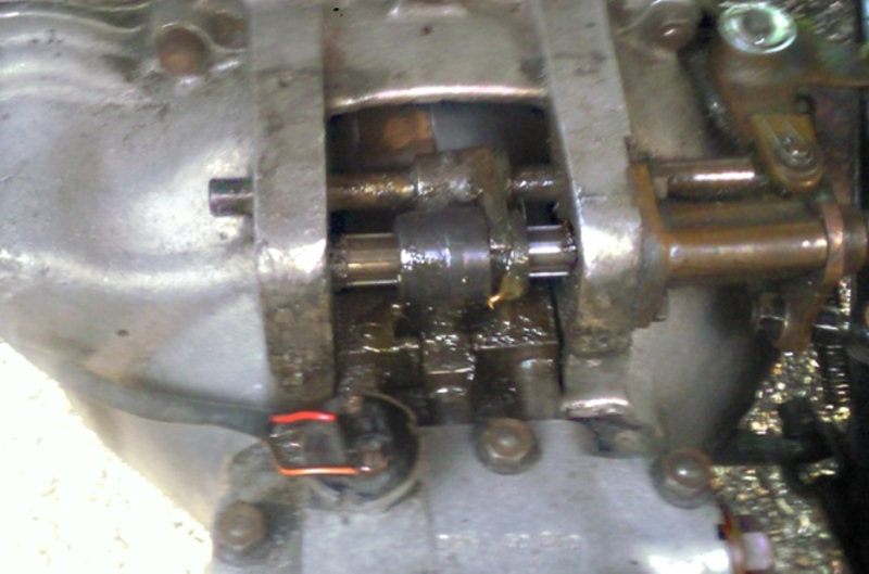
Gear change linkage as removed from the car
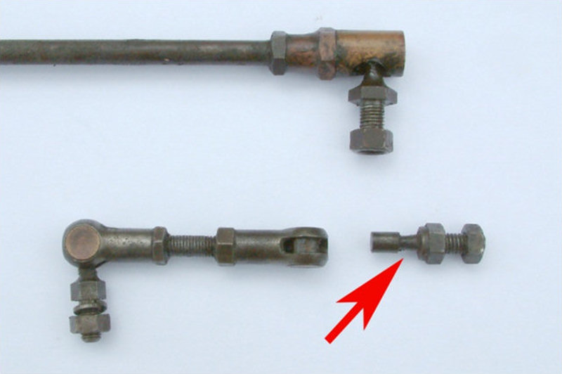
You may have either or both of these joint types in your linkage. The ball type is adjustable but the "Pin" type is not. When removing this lower link, if the end fitting is moved in line with the rod it will come out so be careful that you do not drop it and lose it. There is no adjustment for this joint but no play was found it was just.
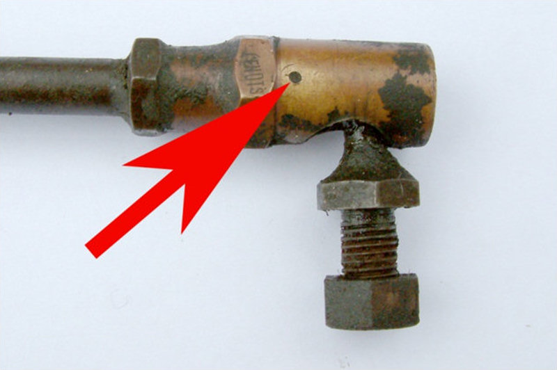
The arrow shows the position of the pin which needs to be removed before the joint can be taken apart. You may be able to get this out with a thin drift. If not it will have to be drilled out, if this is the case a drill press is really needed to make an accurate job of it.
Once the pin is out the two halves of the ball housing can be screwed apart. Once they are separated they will all come out together with a cupped fitting and a double coiled spring washer. If the locknut on the rod is loosened, the remaining brass fitting can be removed. Try to keep the locknut in its original position as a guide to length when re-fitting.
The component parts of the ball joint
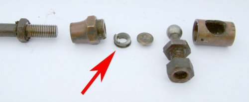
It was found that this spring washer had either broken, worn, or lost its tension. If you can get some new ones re-new them anyway. Clean all the parts and screw them back together. The two brass halves of the joint must be tightened together. If the joint is still loose place a thin washer between the spring washer and the rod end fitting. The aim is to get the two halves of the joint screwed tight together and the ball able to move but with no free play. If you can't get a washer of the correct thickness an alternative is to keep rubbing one on an oil stone until it fits. A rather laborious job but you may as well make a decent job having gone this far, screw the joint back together and make sure that everything is OK. If so now check that a pin can be inserted through the original hole. If not you will have to drill a new hole but move round the joint about 45 degrees to make sure that the new hole does not break into the edge of the original one. Dismantle the joint (yet again) clean out any swarf, grease up and re-assemble. Fit a new pin. Panel pins fit adequately. Push into place, cut off the excess just proud of the barrel and peen over the end. A few of points to watch are;
- The two halves of the joint should be screwed up tight together but they are brass with a fairly fine thread so be careful.
- The pin should be snug fit in its hole. So if necessary adjust the drill size to suite the pins you have.
- The length of the rods may need to be adjusted to get everything working nicely.
After sorting out the joints in the gear linkage there was still a problem selecting all of the gears. This was really due to the play in the pivot arms. To rectify this all of the arms would need to be taken off and bushes made and fitted. One of the arms is mounted in a welded on bracket on the chassis. To be able to drill this out for a new bush the engine would have to be remove to gain enough room for a drill. The problem with the car was that if the linkage was adjusted to get first/second and third/fourth gears reverse was difficult. The selector would not move far enough to the left.

Another way around this problem would be to get more travel from the gear lever. It was found that if the linkage was adjusted to get the selector over to engage with the centre selector rod it would then not travel far enough to the nearside to engage nicely with the reverse gear selector. What follows is a comparatively easy method to counteract the lost motion in the pivots.
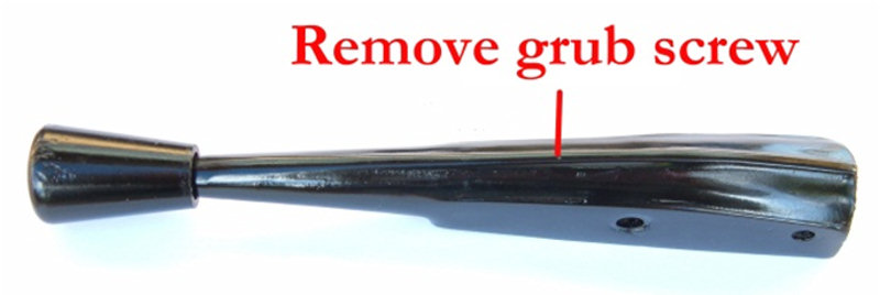
Take off the gear lever and remove the small grub screw. You can then turn the gear knob to remove the small split pin in the rod and slide the rod out. The washer and spring can be left in the housing, but don't lose them.
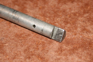
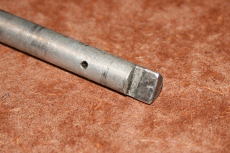
When you have removed the rod take off the end knob so that it doesn't melt when the welding is done. It is the end with the step that we will work on. When the gear lever is pulled across neutral towards the steering wheel the flat part of this step abuts against its stop on the column. When the gear knob is pulled out you can then pull the lever towards the steering wheel to obtain reverse gear. What we are going to do is get a bit more travel between the lever against its stop and its reverse position.
The following paragraph is a guide only.
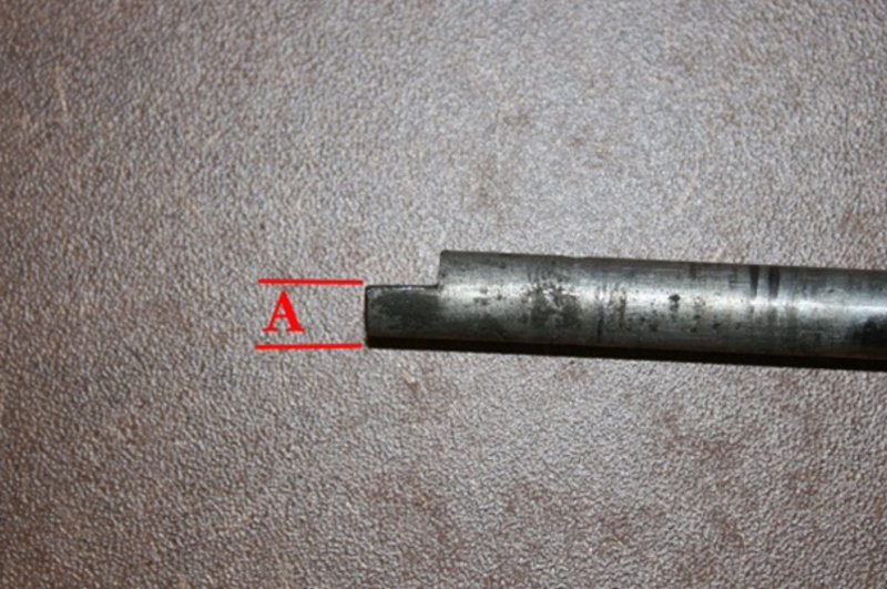
As removed the thickness of this stepped portion "A" was 4.68mm. This step was filled with weld then the end of the rod was ground and filed round so that it fitted in the gear lever. The flat was then filed back until the measurement at "A" was 6.5mm. It may be that your car may need more or less it's easy to file a bit more off but more hassle to add the weld back again. So if in doubt leave this larger, put it all together and try it. If necessary take it apart and file a bit more off. Make sure the "Flat" is where it should be, not just anywhere around the rod.
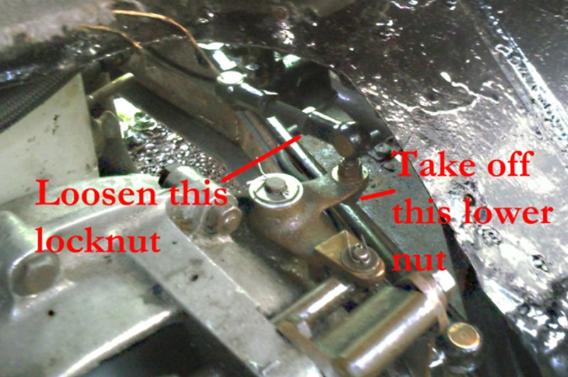
Re-assemble the lever with a little grease. The grub screw should not be tightened up so that it locks the rod up. Once the lever is back on the car you may then have to adjust the linkage. Loosen the lock nut on this rod; remove the lower nut to free the joint from the arm. Our car needed this rod to be un-screwed 3 turns to get it all lined up.
1. When the gear lever is pulled back to its stop the peg on the selector should be in the centre of the middle selector rod. If it isn't, follow the steps above to adjust the linkage. This is the datum point for any adjustment or filing.
2. Move the gear lever towards the dashboard and the selector should move to the far right to engage with its selector rod.
3. Move the gear lever back towards the steering wheel to its stop, pull out the knob and pull the lever back. This should now engage the reverse gear selector. Make sure that the selector is engaging all the rods individually and not trying to move two at once. Check this again after tightening all the nuts up. A spot of paint on the grub screw will lock it up.
Brian Simpson